Perforated timber acoustic surfaces
Perforated Wood Acoustic Panels
A continuous architectural panel with coordinated face holes, rear drilling and acoustic backing.
Through-perforated wood-based panels provide a robust finished surface for walls and ceilings. Hole diameter, pitch, rear cavity and acoustic infill must be selected as one tested assembly.
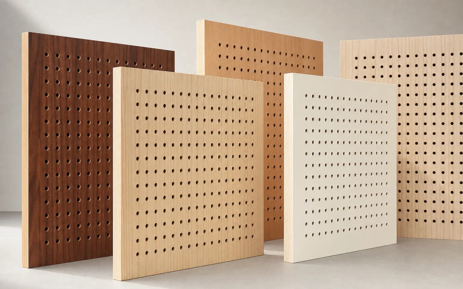 Product range study
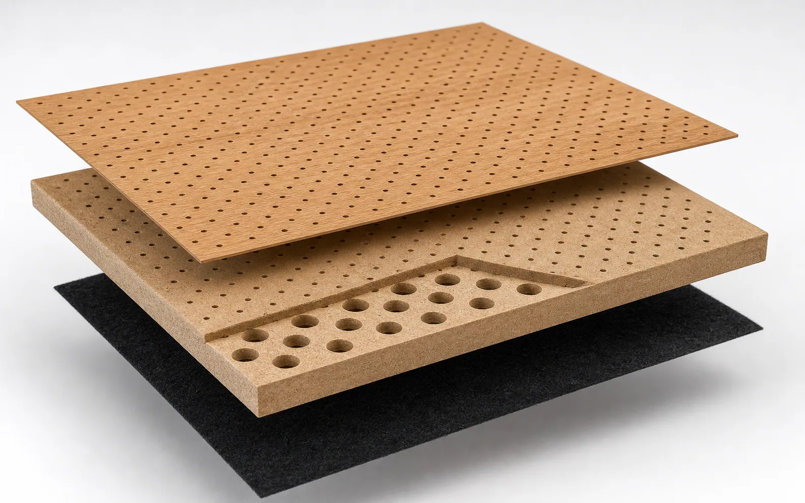
Finish · core · rear tissue
Three coordinated layers, shown at material scale.
The supplied construction combines an architectural finish, a perforated dense panel core and thin black acoustic tissue bonded to the rear. The brochure illustrates 3 mm face holes with larger 10 mm rear drilling for one configuration.
Melamine · Natural veneer · HPL · Paint · Metal sheet · Engineered veneer
Standard, environmental-grade, flame-retardant or moisture-resistant directions are listed in the supplied range.
Thin black backing tissue closes the rear face and forms part of the acoustic build-up.
Material grades, fire classification and acoustic claims require confirmation against the selected product code and current evidence.
Perforation models
Choose the visual rhythm with its declared open area.
Six supplied pattern directions are shown below. Geometry is customizable, but the final drilling code must remain tied to the approved panel and test build-up.
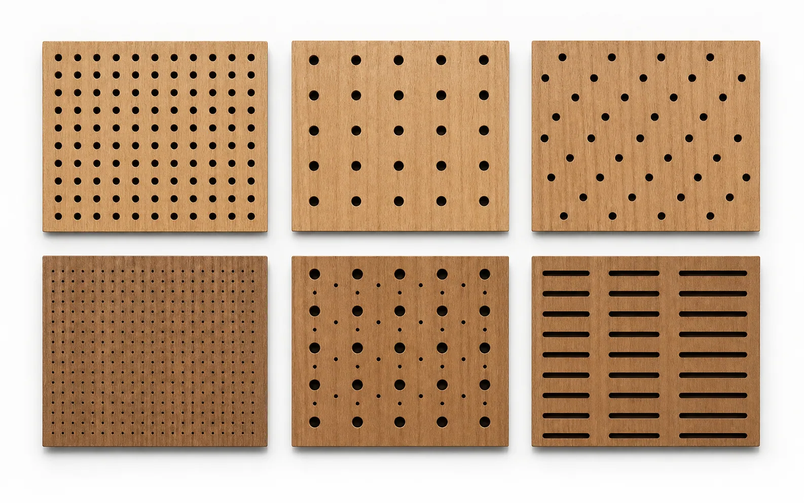
Regular through-hole
16 mm pitch · 6 mm hole
Wide-pitch through-hole
32 mm pitch · 6 mm hole
Staggered through-hole
16 mm pitch · 6 mm hole
Microperforated
8 mm pitch · 1.2 mm hole
Mixed large and small holes
32 mm pitch · 3 and 10 mm holes
Elongated slot
60 × 30 mm module · 6 mm slot
Performance confirmation
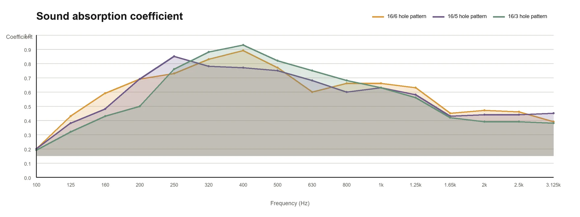
Three hole patterns under one declared test build-up.
The source records a 15 mm perforated panel, 50 mm acoustic infill at 32 kg/m³ and a 50 mm rear cavity.
Acoustic performance depends on the selected thickness, backing material, air cavity and tested installation build-up. Confirm the required specification before ordering.
Values are transcribed from the supplied brochure. Verify the current laboratory report, pattern code and mounting condition before publication or specification.
| Selection basis | Confirmation required |
|---|---|
| Pattern and tested installation build-up | Confirm before ordering |
Wall installation
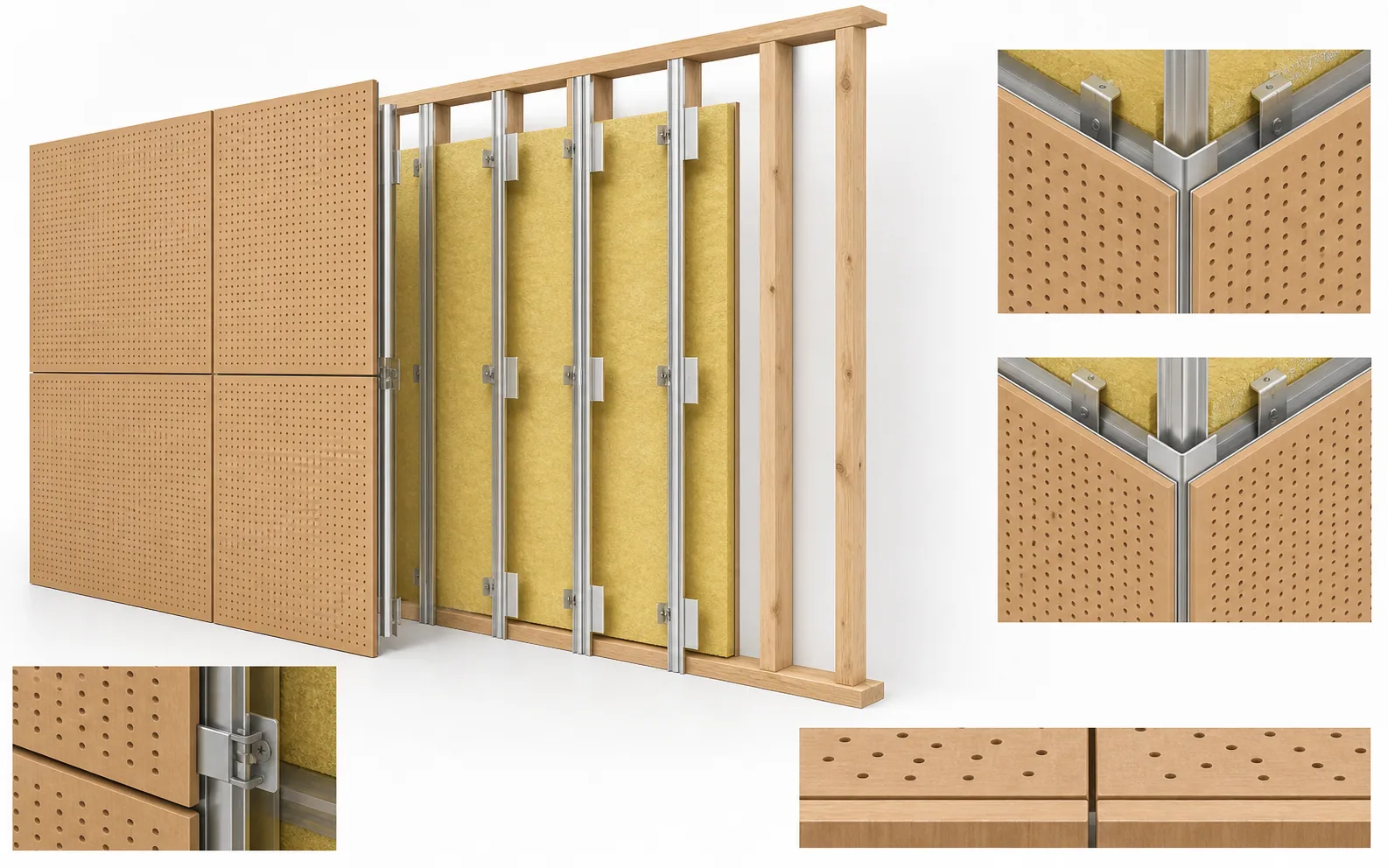
Coordinate profiles, infill, clips, joints and corners as one assembly.
The restored visual follows the supplied wall-fixing relationship and adds enlarged corner and concealed-clip views for specification review.
- 01
Open cartons for at least 48 hours before installation and allow a minimum 3 mm movement allowance between boards.
- 02
Fix aluminium profiles to timber framing or the base board at approximately 600 mm centres.
- 03
Place 32–64 kg/m³ acoustic infill between the framing members.
- 04
Use concealed clips to secure the perforated panels to the profiles; keep a controlled 2–3 mm joint allowance.
- 05
When installing horizontally, orient the panel notch downward and build upward from the lowest course.
Application gallery
Perforated timber surfaces across six architectural settings.
These high-resolution visual studies show the intended installed effect of flush perforated wood panels. They are design references, not completed JHS projects.
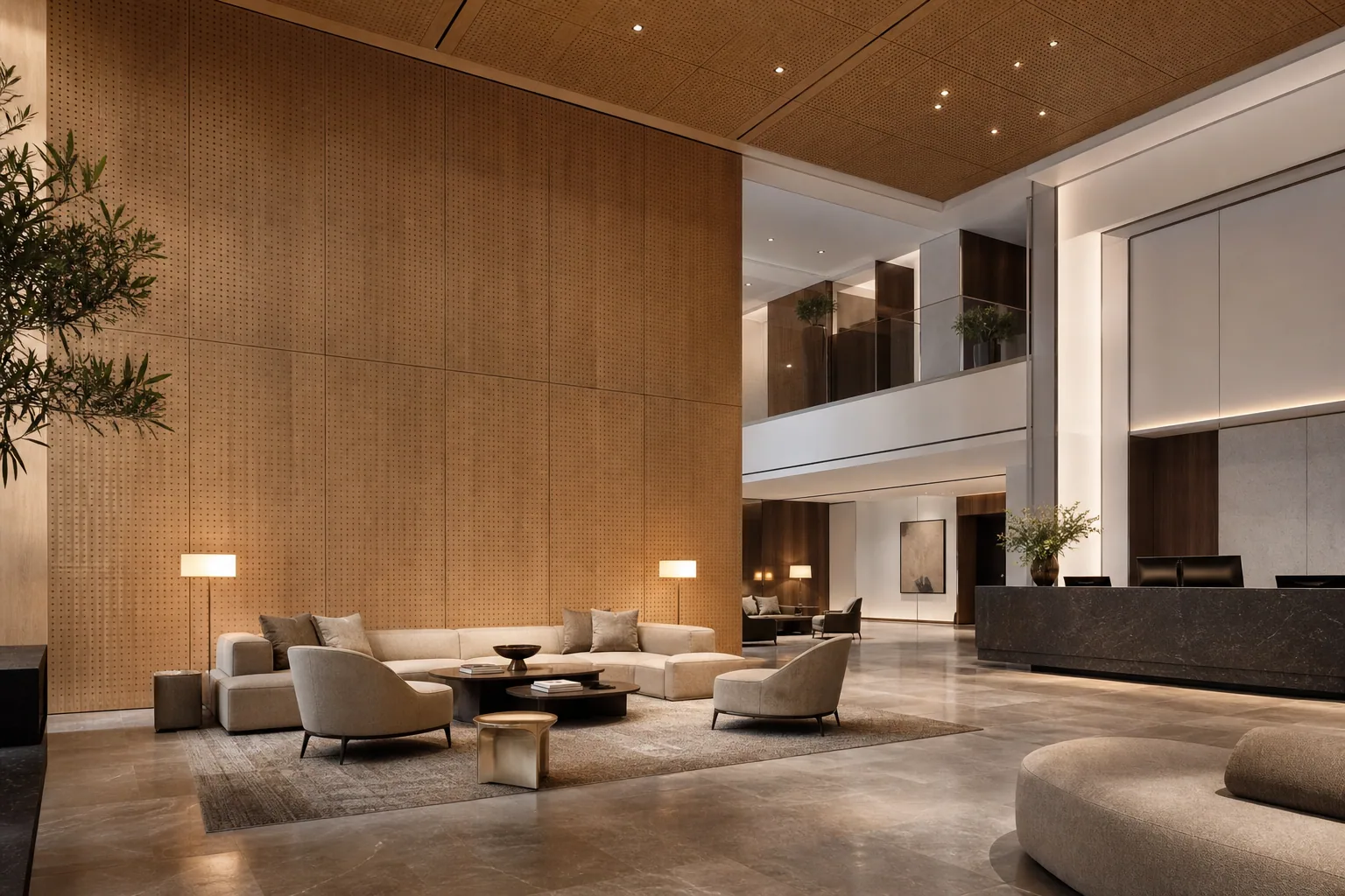
Five-star hotel lobby
Large perforated wall and ceiling fields bring material warmth to high-volume hospitality interiors.
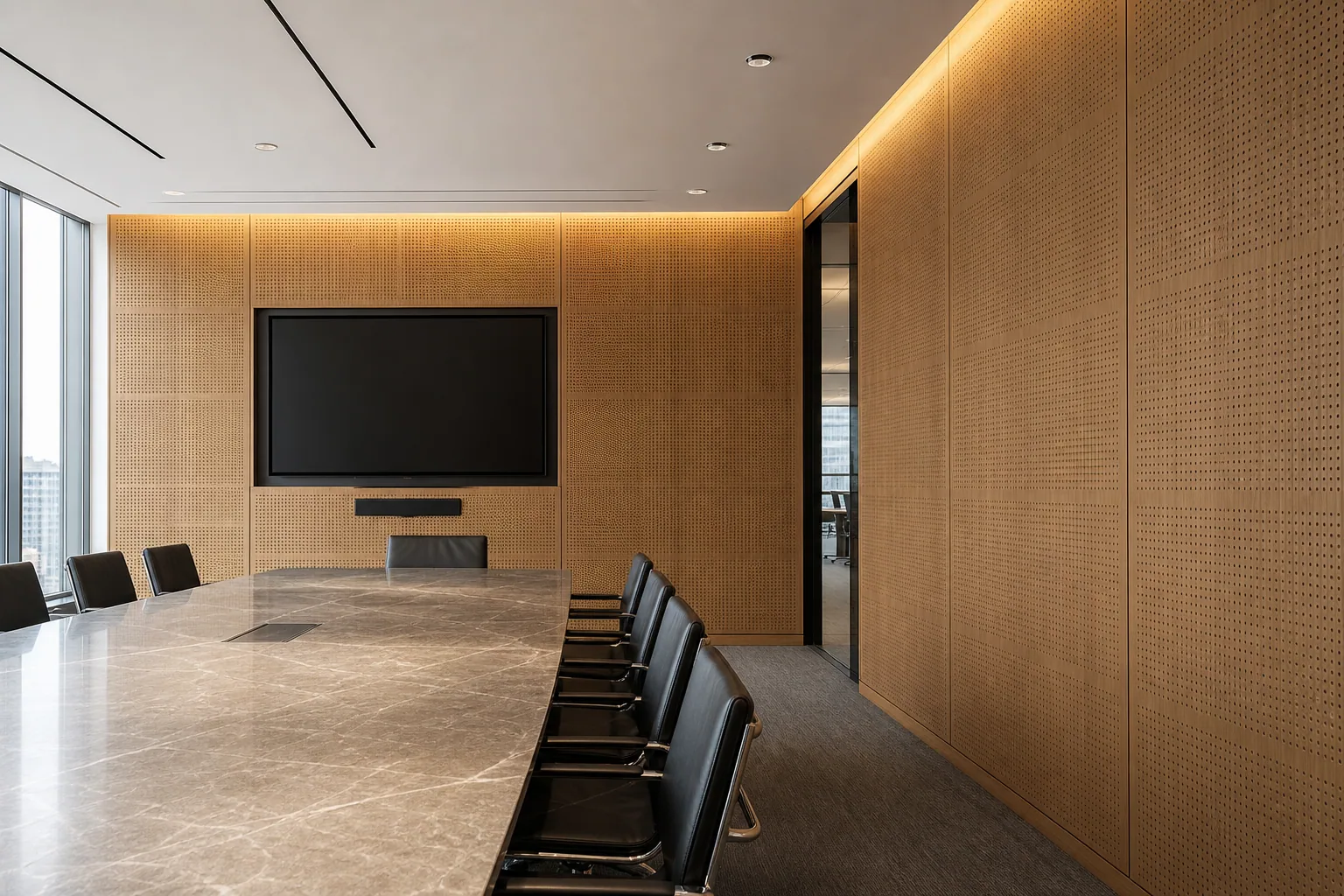
Executive boardroom
A precise modular surface for presentation walls and focused meeting environments.
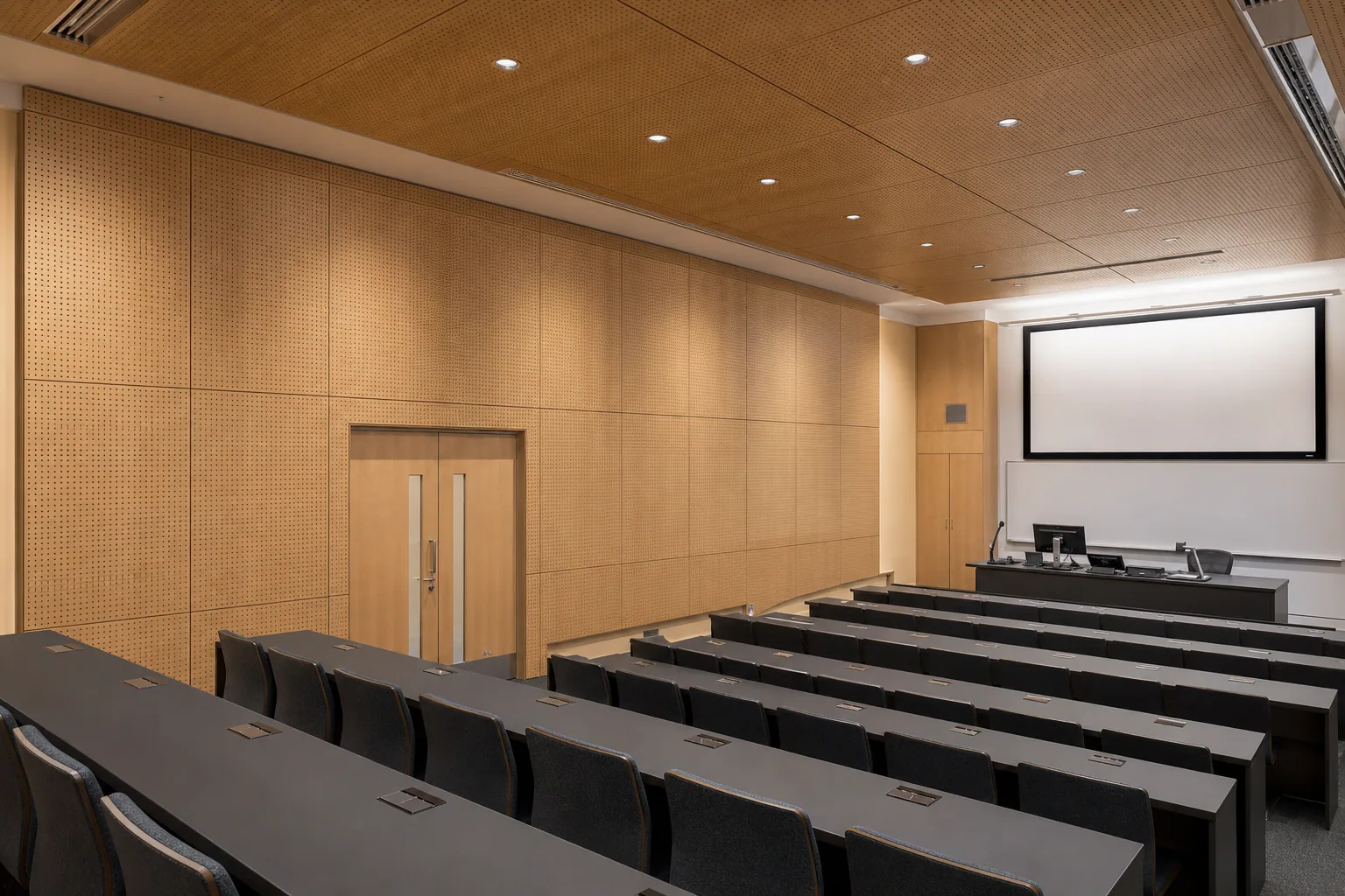
University lecture hall
Robust perforated wall and ceiling zones support speech-led teaching spaces.
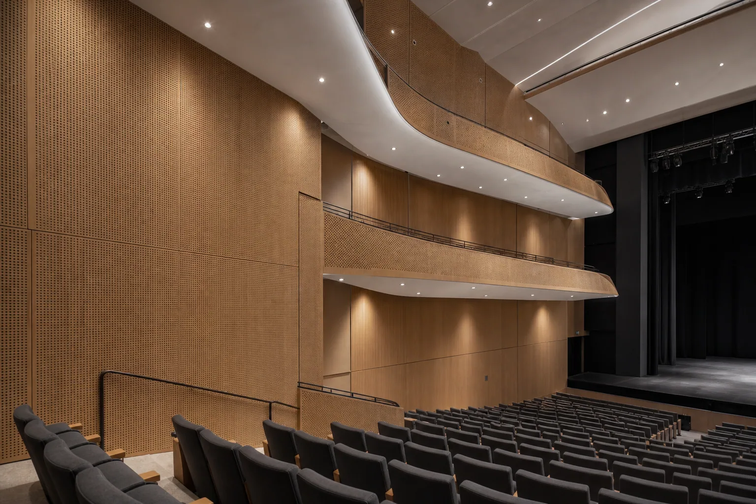
Performing arts auditorium
Perforated timber panels coordinate side walls and balcony fronts at civic scale.
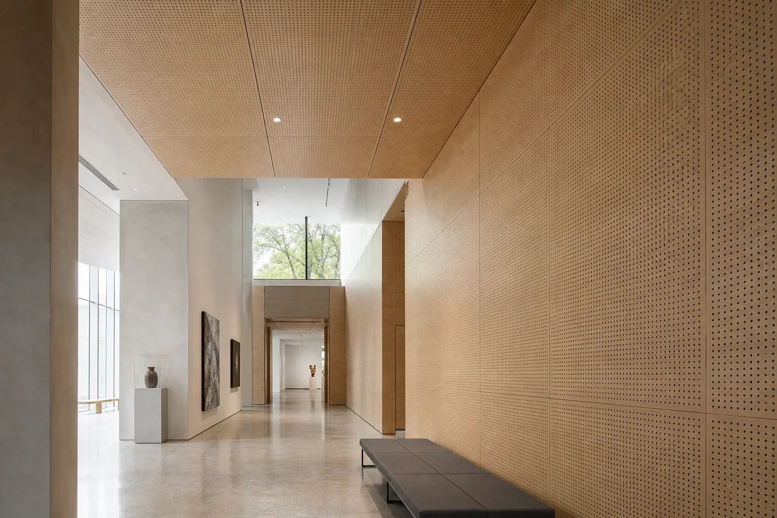
Museum gallery
Quiet, continuous timber planes bring acoustic control to galleries and cultural circulation spaces.
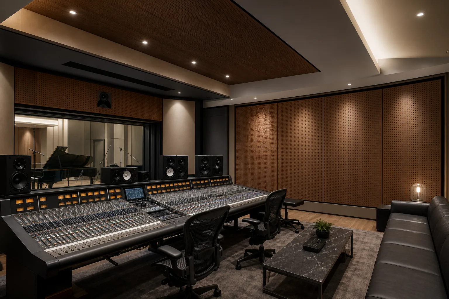
Recording studio
Flush walnut panels integrate with the wider acoustic design of a professional control room.
Frequently asked questions
Questions before selecting Perforated Wood Acoustic Panels.
Clear the material, mounting and evidence questions before the product is released into a project.
Select the hole pattern, open area, timber finish, backing and edge treatment as one verified panel configuration.
Confirm the current product code, dimensions, finish, mounting method, acoustic test conditions and fire evidence against the exact proposed build-up.
The same finish can serve walls or ceilings only where the approved backing, support grid and service coordination are suitable.
Send the room type, drawings or elevations, substrate, target programme and any required compliance information. The project team can then identify the documents and sample route needed for review.